Whats the difference between a client and an interface?
A client is basically one “physical” computer, which is present inside a network. But one client can have multiple network interfaces to, for example, communicate with multiple different networks.
Can an interface have multiple IP addresses?
Yes! In IPv6 it is “default” to have a “Link Local” and a “Globale” address, but also IPv4 can have multiple IP addresses.
As mentioned in the previous posts we know, what IP addresses are and how an IP network is basically built.
Lets stay with the example from “What is an IP address?” where an IP address is similar to a house address. Therefore we can make the analogy, that a port ist a special entry (door, window or something the like) of a house, which belongs to a special application.
Port numbers can range from 0 to 65535 where some of these are predefined.
System Ports (0 – 1023)
Predefined / standardized ports
User Ports (1024 – 49151)
User can define (if not already occupied by another application) their own ports for their specific application
Dynamic Ports (49152 – 65535)
This area is used primarily by the operating system for dynamically generated port assignments.
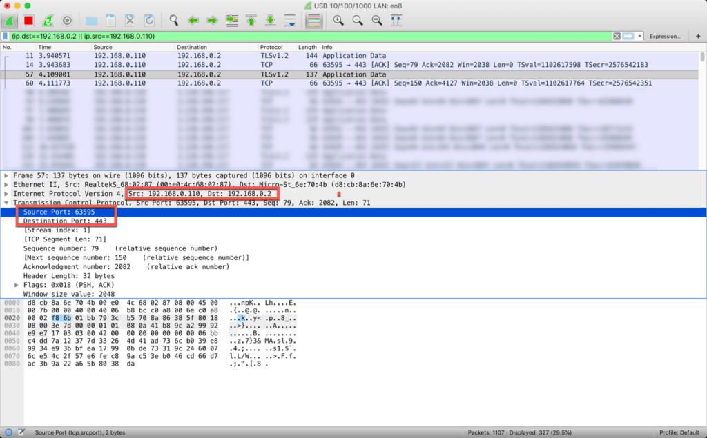
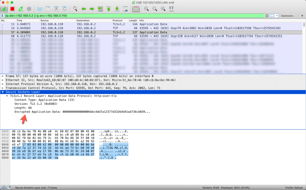
In the following screenshot you can see a section of the application “Wireshark”. In this screenshot you can see an HTTPS request which has been sent from a clients (192.168.0.110) automatically generated port 63595 to my server (192.168.0.2) to the default HTTPS port 443.
Since all my websites are secured via HTTPS we can’t see any more human readable data (like z.b. the HTTP Protokoll) since all the data is being encrypted via TLSv1.2.
To standardize the usage of commonly used applications specific ports have been predefined.
Lets image we only have 1 IPv6 address for our client which for example has been automatically generated by SLAAC (which contains the MAC-Address of the network card).
If this IPv6 address is being used to connect to the internet it would be very easy for tracking tools to identify you as an individual and create a profile.
Thats why random temporary IPv6 addresses are being generated to establish connections to the internet. Since these temporary IPv6 addresses are being deleted and regenerated periodically (depends on the system how often) its pretty hard for tracking tools to create a profile just on an IP address basis.
Secured IPv6 address
ATTENTION: I haven’t verified this information, therefore its just my speculation!
Secured IPv6 addresses keep unique for one interface inside a specific network.
For example you will get the same secured IPv6 address in your home network or you company network to access e.g. a special network share.
Currently this “secured” IPv6 feature is only visible by default on MacOS (June 2019)
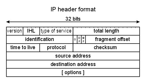
The basis for the communication in a network is a way to uniquely identify different devices. For exactly that purpose the “Internet Protocol” (short IP) has been developed.
An IP-Address is a unique number, which identifies a device inside the currently used network. This number can be something like:
IPv4: 192.168.0.10 IPv6: fe80::884:34ae:8eaf:a586
The detailed difference between IPv4 and IPv6 can be looked up in the linked posts.
But let’s keep it simple. An IP-Adresse can be seen as a “postal address” of your house to differentiate your house from your neighbours house. The only difference is that its not “Mainstreet 3, 8430 Leibnitz”, instead its “192.168.0.2” and that its not about houses, its about IT devices.
Why did we have to develop IPv6?
Basically IPv4 allows a maximum of 4.294.967.296 (232) devices, which in the grand scheme of the planet earth and its currently 7.7 billion people is not quite sufficient.
Therefore IPv6 was developed and allows a maximum of 340.282.366.920.938.463.463.374.607.431.768.211.456 (2128) devices which should suffice for quite some time.
Why was the internet protocol developed anyway?
Before the internet protocol it was not possible to connect 2 different network systems or let 2 computers from 2 difference network systems communicate with each other.
With the internet protocol it should be as easy as possible to connect multiple computers and networks with each outer without having to adjust things like baud rates or the need to “hardcode” specific address codes.
Main tasks of the internet protocol
Address allocation
Commands to build and breakdown connections
Control of data flow via start und stopp commands
Error detection via checksums, time-outs etc.
Automatic error correction when an error has been detected
Main traits of the internet protocol
Its independent on the architecture
Connection to and from all network clients possible
dynamic routing
The main tasks of the internet protocol have been split up into single “layers” – which build the Open Systems Interconnection model, in short OSI.
IPv4 has been defined 1981 in the RFC 791. It is the first version, which has been used worldwide to connect far away computers and was a main factor of the development of the “internet“.
The IPv4 address consists of 32 bits which allows a maximum of 4.294.967.296 (232) unique addresses.
Network- and Host devision
An IP address consists of 2 parts – a Network and a Host part. The devision is defined via the so called “subnet mask”.
Example: 24-Bit network
Subnet
=
11111111.11111111.11111111.00000000
(255.255.255.0)
Network part
=
11000000.10101000.00000000
(192.168.0)
Network address
=
11000000.10101000.00000000.00000000
(192.168.0.0)
First address
=
11000000.10101000.00000000.00000001
(192.168.0.1)
Last address
=
11000000.10101000.00000000.11111110
(192.168.0.254)
Broadcast
=
11000000.10101000.00000000.11111111
(192.168.0.255)
Amount of available addresses: 28 − 2 = 254
It is 28, because the whole IP address has 32 bit and 24-Bit have been “occupied” by the subnet. Thats why we only have 8 bit left.
The network address (192.168.0.0) and the broadcast address (192.168.0.255) are always subtracted from the maximal amount of available addresses because these 2 shouldn’t be used as client addresses.
Example: 16-Bit network
Subnet
=
11111111.11111111.00000000.00000000
(255.255.0.0)
Network part
=
11000000.10101000
(192.168)
Network address
=
11000000.10101000.00000000.00000000
(192.168.0.0)
First address
=
11000000.10101000.00000000.00000001
(192.168.0.1)
Last address
=
11000000.10101000.11111111.11111110
(192.168.255.254)
Broadcast
=
11000000.10101000.11111111.11111111
(192.168.255.255)
Amount of available addresses: 216 − 2 = 65,534
Reserved IP address spaces
Not everything of the maximum 232 available IP addresses have the same “functionality”. Instead some areas have a special cause. The most import are:
IPv6 has been defined in the RFC 2460 in 1998 and replaced with the RFC 8200 in 2017. It is the successor to IPv4 which shows many problems as time went on using it in larger amounts.
Notation
Since IPv6 consist of 128 bit a decimal notation similar to IPv4 wouldn’t be very efficient. Thats why the decision has fallen onto a hexadecimal notation.
2001:0db8:85a3:08d3:1319:8a2e:0370:7344
Leading zeros inside a IPv6 block can be left out. Example:
2001:0db8:0000:08d3:0000:8a2e:0070:7344
turns into
2001:db8:0:8d3:0:8a2e:70:7344
If 2 or more blocks only containing zeros appear right after each other they can be replaced with two :
Example:
2001:db8:0000:0000:0000:0000:1428:57ab
turns into
2001:db8::1428:57ab
Notice the two : between db8 and 1428.
But this reduction is only allowed to happen once in the whole IPv6 address! Example:
2001:0db8:0:0:8d3:0:0:0
can only turn into
2001:db8:0:0:8d3::
or
2001:db8::8d3:0:0:0
werden.
Thats why the following address is not a valid address:
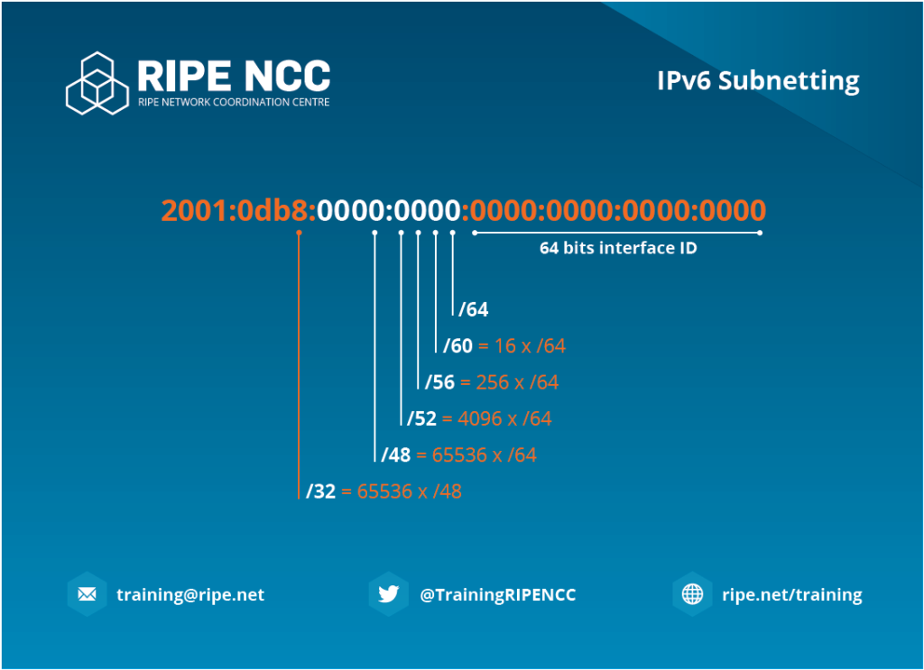
Basically you can create more subnets after /64 but you will lose a pretty important feature – the “Stateless Address Autoconfiguration” (SLAAC). See bellow for further information.
Link Local and Global address
After connecting an interface to a network it is now default In IPv6 to automatically create a “link local” and (if a IPv6 prefix is present) a “global” address.
The “Link Local” address is used – as you probably already expected – only for the locally connected network. This address is always a part of the subnet fe80::/64
The “Global” address is used – as you probably already expected too – for the “global” network aka the “Internet”. But this address only appears if the connected router has a correctly configured IPv6 prefix.
Additionally there are “temporary” and “secured” IPv6 addresses for security reasons. What these are and why they are needed can be looked up right HERE.
New features of IPv6
Larger amount of available addresses
An IPv6 address has 128 bits – IPv4 only has 32 bits.
In comparison IPv6 has 340.282.366.920.938.463.463.374.607.431.768.211.456 (2128) and IPv4 only 4.294.967.296 (232) total available addresses.
Stateless Address Autoconfiguration (SLAAC)
To automatically get an IPv4 address assigned to your device there needs be a “DHCP” server present in the current network. Most of the time this is built into everyones wireless router.
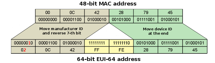
But in a IPv6 network with at least a subnet size of /64 the MAC address of each client can be used as part of the IPv6 address. This is used for the “link-local” as well as the “global” address.
The following illustration just shows how a 48 bit MAC address and the 64 bit “link-local” prefix is used to automatically create an IPv6 address.
The “Internet Protocol Security” (IPsec) is a protocol residing in the 3rd layer of the OSI-Layer Models which allows the encryption and authentication of IP packets.
Basically everyone know what HTTPS, SSL and TLS are but these protocols work on higher OSI layers (HTTPS in the 7th and TLS in der 4th). Thats why “someone” can still manipulate data in the 3rd layer.
Thats why the IPsec protocol has been integrated into the IPv6 standard.
Conservation of the “Point-to-Point principal“
The “Point-to-Point principal” says, that only the endpoints in a connection are allowed to perform active protocol operations, not the stations between the 2 clients. A global unique IP address per client is a requirement for that.
In the current state of the IPv4 network this is not possible since not every client in the world has a unique IPv4 address.
Reserved IPv6 spaces
As well as in IPv4 there are reserved spaces, which are used for specific “functionalities“.
There are also special areas which are used just for “converting” IPv4 into IPv6 addresses such as z.B. 2002::/16 for the 6-to-4-Tunneling (see RFC 3056).
What Unicast and Multicast are can be looked up HERE.
An IP address can be split into 2 different parts – the network- and the host-part.
When/How this partition is happening is defined via the netmask, which is built by the same 32 bit as an IP address (therefore in a range between 0.0.0.0 and 255.255.255.255)
The network part can be seen from left to right, the host part from right to left.
Example
Netmask 255.255.255.0 – Short /24 Available IP addresses in this subnetwork: 254
This means if we define a network with 192.168.0.0 the first 3 numbers 192.168.0 are the network part and the last number 0 is the host part.
Theoratically there are 256 IP addresses available, but the first and last IP address inside a subnet are predefined. With our example of a /24 subnet
That why we “only” have an actual useable area between 192.168.0.1 and 192.168.0.254 which sums up to a maximum of 254 usable addresses.
If we want to have more than 254 concurrent clients inside a given network we have to decrease the netmask. See the following table:
Netmask
usable IPv4 addresses
Netmask visualized as bits
255.0.0.0(/8)
max. 16.777.214
1111’1111.0000’0000.0000’0000.0000’0000
255.240.0.0 (/12)
max. 1.048.574
1111’1111.1111’0000.0000’0000.0000’0000
255.255.0.0 (/16)
max. 65.534
1111’1111.1111’1111.0000’0000.0000’0000
255.255.240.0 (/20)
max. 4094
1111’1111.1111’1111.1111’0000.0000’0000
255.255.248.0 (/21)
max. 2046
1111’1111.1111’1111.1111’1000.0000’0000
255.255.252.0 (/22)
max. 1022
1111’1111.1111’1111.1111’1100.0000’0000
255.255.254.0 (/23)
max. 510
1111’1111.1111’1111.1111’1110.0000’0000
255.255.255.0 (/24)
max. 254
1111’1111.1111’1111.1111’1111.0000’0000
255.255.255.128 (/25)
max. 126
1111’1111.1111’1111.1111’1111.1000’0000
255.255.255.192 (/26)
max. 62
1111’1111.1111’1111.1111’1111.1100’0000
255.255.255.224 (/27)
max. 30
1111’1111.1111’1111.1111’1111.1110’0000
255.255.255.240 (/28)
max. 14
1111’1111.1111’1111.1111’1111.1111’0000
255.255.255.248 (/29)
max. 6
1111’1111.1111’1111.1111’1111.1111’1000
255.255.255.252 (/30)
max. 2
1111’1111.1111’1111.1111’1111.1111’1100
255.255.255.254 (/31)
2 as P2P
1111’1111.1111’1111.1111’1111.1111’1110
255.255.255.255 (/32)
None
1111’1111.1111’1111.1111’1111.1111’1111
But of course you can use multiple subnetworks and combine them with each other via a Router.
Why do we need subnetworks?
Subnetworks are needed so clients know if an IP-packet should be redirected only in the local network or if it should be handled by a router (and therefore redirected to another network).
But a “Computer 3″ with the IP 192.168.1.1/24 can’t communicate with”Computer 1” or “Computer 2” because it is located in another subnet. See subnet and netmask for more details.
A switch can’t control or change the network flow like a router.
Theoretically you can compare a switch with a power distributor.
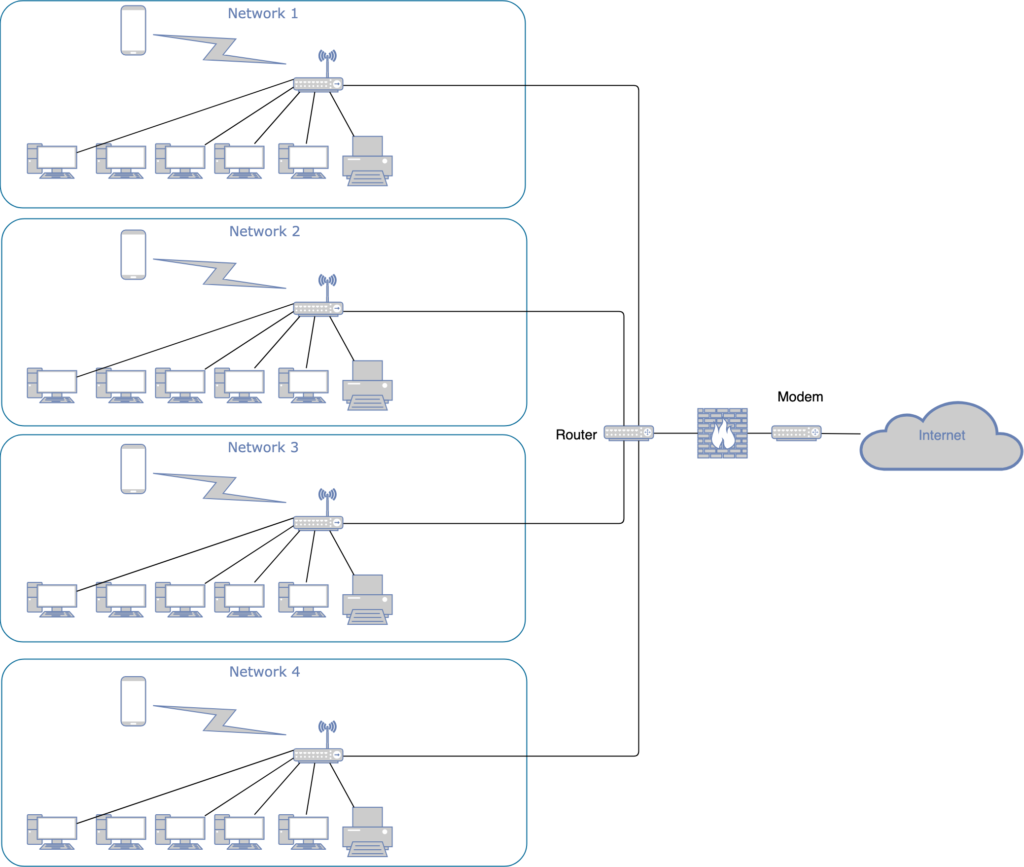
A router connects multiple networks with each other, so that computers from 2 or more different networks can communicate with each other.
In the example above every computer in network 1 to 4 can communicate with each other and/or the internet (dependent on how the router is configured).
Router “work” in the 3 layer of the OSI model (“Network Layer”). Information like IP-addresses of the sender and recipient, Time-To-Live or protocol typ are present in this layer..
The router knows which packets should be sent through which interface due to the IP address of the sender and recipient.
What are WAN and LAN?
Since multiple networks are connected to a router we have to determine which of these networks are “local” and which are “wide”.
Thats why we have a “Wide Area Network” (WAN), which describes a global network area, and a “Local Area Network” (LAN), which describes a private network area.
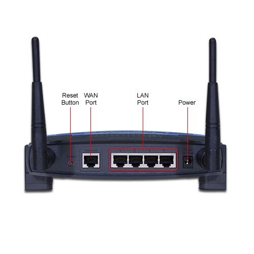
Most of the time a router has a specially marked “WAN”-Port, which is usually used for the incoming internet connection.
Example
LAN networks: Your home, company, school WAN network: The whole network present in the world
The WAN-Port is used for an incoming internet connection and the LAN-Ports are used for your clients and/or more routers or switches which define your local network structure.
Many routers integrate a modem, which basically handles the authentication to your “Internet-Service-Provider” (ISP).
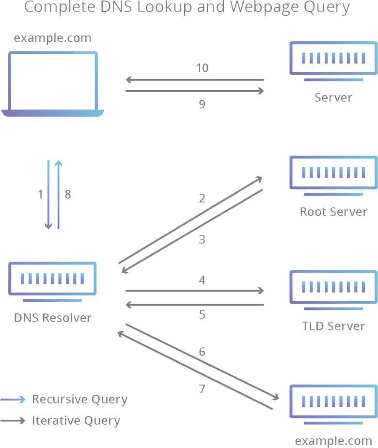
The “Domain Name System” (short DNS) is kind of a telephone book for the internet.
Basically the communication between 2 computers happens over IP addresses. Due the the fact, that these (and especially IPv6) addresses are not easily memorable for humans so called “domain names” can be connected to these IP addresses.
Therefore a DNS-Server “translates” a request like “google.com” into the IP address 172.217.18.67 (v4) and 2a00:1450:400d:802::200e (v6).
Detailed information
The 8 steps of a DNS lookup:
A user enters the address “example.com” in a web browsers. This creates a request to the next available “DNS recursive resolver”.
This “resolver” creates an additional request to the next available “DNS Root Server” (.)
The “Root Server” redirects this request to next available “Top Level Domain (TLD) DNS Server” (like z.B. “.at” or “.net”). Due to the fact, that our request contains the domain “example.com” the DNS resolver gets the address of the next available “.com” TLD DNS Servers.
The “resolver” now sends the request to the newly available “.com” TLD DNS Server.
The TLD DNS Server returns (if available) the IP address of the Domain Name Server for “example.com”.
Finally the “resolver” sends a request to the specific Domain Name Server.
Finally the IP address for “example.com” will be returned to the “resolver”.
The “resolver” sends this now resolved IP address for the requested domain back to the client.

